Set the Wind Tunnel Geometry
1. Select the Block Mesh tab
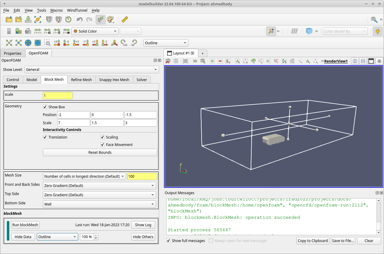
After clicking on the Block Mesh tab, the 3D RenderView updates to display the Ahmed Body along with the outline of an axis-aligned rectangular solid that represents the geometry to use for the wind tunnel. To see the full geometry, use your mouse’s scroll button to zoom out or click the “Reset Camera” toolbar button ( ![]() ).
).
2. Adjust the geometry
To resize and reshape the wind tunnel geometry, use the numerical fields in the Geometry section of the Block Mesh tab. Enter these numbers in the Geometry section:
Position: -2.0   0.0  -1.5
Scale:     7.0   1.5   3.0
3. Edit the other blockMesh inputs
Below the Geometry section, find the Bottom Side field. Select the dropdown list next to it and set it to the Wall value.

At this point, save your work using the menu item.
4. Run blockMesh
In the blockMesh section at the bottom of the tab, click the Run blockMesh button to launch the OpenFOAM blockMesh utility. Modelbuilder will display the log messages in a pop up dialog. The process should only take a few seconds, and you can close the dialog when you see the mesh information followed by a line with the word “End”.
To see the results of the blockMesh run, click the Load Data button in the control view. With the default mesh size setting, the resulting mesh has 100 x 20 x 20 cells.

5. Display Outline Representation
One last thing before moving to the next step: change the block mesh display from the “Surface” to “Outline” representation. To do this, find the dropdown control to the right of the Hide Data button in the control panel and change the dropdown value to Outline. This step is just for convenience, to let us see the overall bounds of the wind tunnel in the next step (“Refine Mesh”).