Set the Wind Tunnel Geometry
The next step is to setup the geometry of a virtual wind tunnel to surround the wing section model.
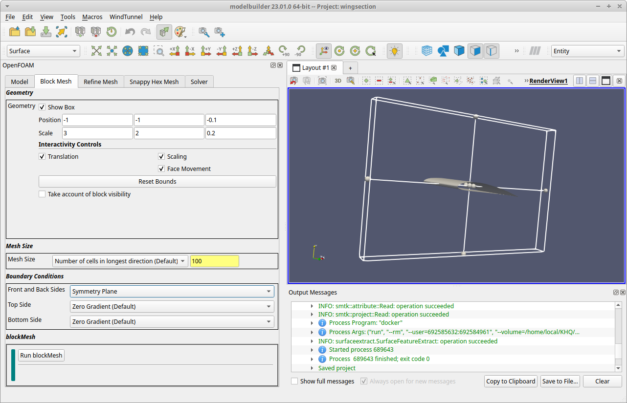
1. Select the Block Mesh tab
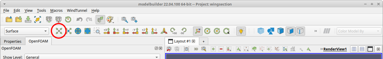
When you click on the Block Mesh tab, the 3D RenderView updates to display the wing section object along with the outline of an axis-aligned rectangular solid that represents the geometry to use for the wind tunnel. To see the full geometry, you can use your mouse’s scroll button to zoom the view out. You can also click the “Reset Camera” button ( ![]() ) to zoom to a position where you can see all of the displayed geometry.
) to zoom to a position where you can see all of the displayed geometry.
2. Adjust the geometry
The rectangular outline is an interactive widget that you can resize and reshape by dragging the small spherically-shapped grabbers. We want to do two things: (i) extend the box in the negative Y direction so that the wing section is centered in Y, and (ii) reduce the size in the Z direction because the wing cross section is uniform and, therefore, the calculated fields are uniform in that direction.
When you adjust the widget size/shape in the RenderView, you will see the numerical fields in the Block Mesh tab update, specifically next to the Position and Scale labels. These fields are kept in sync (bidirectionally) with the widget. For this example, enter these numbers in the Geometry section:
Position: -1,  -1,  -0.1
Scale:     3    2    0.2
3. Edit the other blockMesh inputs
Below the Geometry section is a Mesh Size section with one field with the same name. We can specify the mesh size in several ways. Leave the default settings as is; they will generate a 3D grid with 100 elements in the longest direction (X in this project) and internally set a mesh size in the other coordinate directions to produce voxels with (approximately) equal edge lengths.
Below that is a Boundary Conditions section for assigning the walls of the wind tunnel. Our example always uses the “Left” side (YZ plane at min X) as the inlet surface and the “Right” side (YZ plane at max X) as the outlet surface, so these are not included in the user interface. The Front and Back Sides are the XY planes at min/max Z and, for our application, are always set to be the same. The Top Side is the XZ plane at max Y and the Bottom Side is the XZ plane at min Y.
For the wing section example, we only need to update one field: select the dropdown list next to and select the Symmetry Plane value.
At this point, save your work using the menu item.
4. Run blockMesh
The bottom section of the tab is a control view labeled blockMesh, which is used to run the OpenFOAM application with the same name. The blockMesh utility decomposes the rectangular geometry specified for the wind tunnel into a grid of three-dimensional, hexahedral blocks. The blockMesh utility can construct meshes with features such as grading and curved edges, but our example works fine with a linear edges and a uniform grid.
Click the Run blockMesh button to launch the OpenFOAM blockMesh utility. Modelbuilder will display the log messages in a pop up dialog. The process should only take a few seconds, and you can close the dialog when you see the mesh information followed by a line with the word “End”.
To see the results of the blockMesh run, click the Load Data button in the control view, which will cause modelbuilder to load and display the mesh geometry.

With this step complete, we can skip the Refine Mesh tab and go straight to the Snappy Hex Mesh tab next.